The picture shows the Bush tv22 in operation over the below-described standards converter

Converter for 405 or 441 standard definition TV with London modulator.
Useful Standards Converter and Modulator Info
Peter's Nostalgia Site
SO YOU WANT TO BUILD A STANDARDS CONVERTER
This blog replaces the this site is no longer available.
determination is questionable for some readers the sense of such a device, so here first some background information for those interested.
The 405 line system in 1936 put into operation in England and was, with minor changes (441 lines) then introduced us and was then European standard.
The 441 line standard was with us until the end of the 2nd World War II used 50's in France until the early years. In England it was only switched off in the 80s. Therefore, one can in England and still very beautiful 405 TV lines bid at reasonable prices.
After the 2nd World War, we have naturally adapted to the American standard. In adapting to the 50Hz AC line frequency in Europe, they agreed on 625 lines (CCIR) and this is still the usual standard.
Who now a 405 / 441 TV lines of a now standard 625 line source, ie DVD, satellite or DVB-T receiver, video recorder, digital camera, etc. would like to run, so you need a standard converter that converts the row
frequency. This can feed a small TV channel (modulator) with the one the signal to the antenna input of the TV. Since most of the 405 lines are matched devices on the London or channel can be tuned, I have built a modulator for the channel in the standard
Converter.

This standard analog converter works! Heart Two bucket brigade IC's which is omitted by skillfully switching delay time and the two output signals, each third line.
The contents of the omitted line is first attached to a bucket for a special switching and overlapping procedures. The remaining lines are stretched to fill the gap. Thus, the number of lines is reduced by one third (416 2 / 3 lines) and you can operate the TV 405/441Zeilen without any modification.
The modulator at the output has very sophisticated 6 - pole vestigial sideband filter.

circuit:
page 1
Journal 2
Sheet 3
Sheet 4
Sheet 5
sheet 6 modulator
Journal 7 new timing
Sheet 8 power supply and sockets
Journal 9 Block diagram
sheet 10 PLL

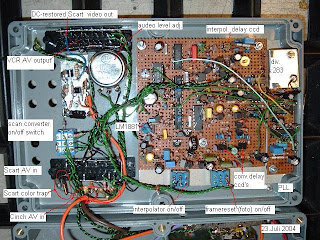
Images of individual components
Converter Boards in housing top
PLL
clock oscillator and synchronous divider
open modulator
oscillators and mixers
41.5 MHz oscillator (sound)
tone modulator
Q67
clamping
Scart video output

oscillograms
Alternate reading of 64μs line with the signal f
output signal of the first bucket
output signal of the second bucket
switching between the outputs with the signal f is the 96μs line sequence
switching signal for the overlay level (Interpolator) oscillogram basis Q26
half line pulses at the base of Q38
V pulse at the base of Q38
The next blog then explain the developments to MK IV. In the next blog will
the row storage stage, the so-called interpolator explained.
last updated on 15 June 2009
This work is licensed under a Creative Commons Attribution
-Noncommercial-No Derivative Works 2.0 United States License .